
In Revit, a curtain wall is assembled from two family types that operate under different rules. The curtain wall type, grid lines, and mullions are system families — built into Revit, controlled through type properties, not loadable from external files. Curtain wall panels can be either built-in system panel types or external loadable families hosted in grid cells. Confusing which type controls what is the most common reason curtain wall edits fail silently in Revit.
Revit Curtain Wall Uses Two Family Types — and They Control Different Things
Revit separates families into two categories at the application level, and the distinction matters in practice. System families — walls, floors, roofs, curtain walls — are defined inside Revit itself. System families cannot be loaded from an external file, cannot be saved as a standalone .rfa, and can only be moved between projects using the Transfer Project Standards command — this is a fundamental constraint of Revit's architecture, not a configurable setting. The curtain wall type is a system family. Curtain wall grid lines and mullion types are also system families.
Loadable families are external .rfa files — created in the Family Editor, loaded into projects on demand. In curtain wall workflows, the panel families that populate grid cells are loadable: built from the Curtain Panel.rft template, loaded into the project, and either set as the default panel type in the curtain wall system type or placed in individual cells by selection.
The consequence: when a curtain wall panel looks wrong, the fix lives in the loadable panel family — not in the curtain wall system type. Editing the system type changes grid rules and default assignments. It doesn't touch panel geometry.
The Curtain Wall System Type Controls Grid Layout Rules — Not Panel Geometry
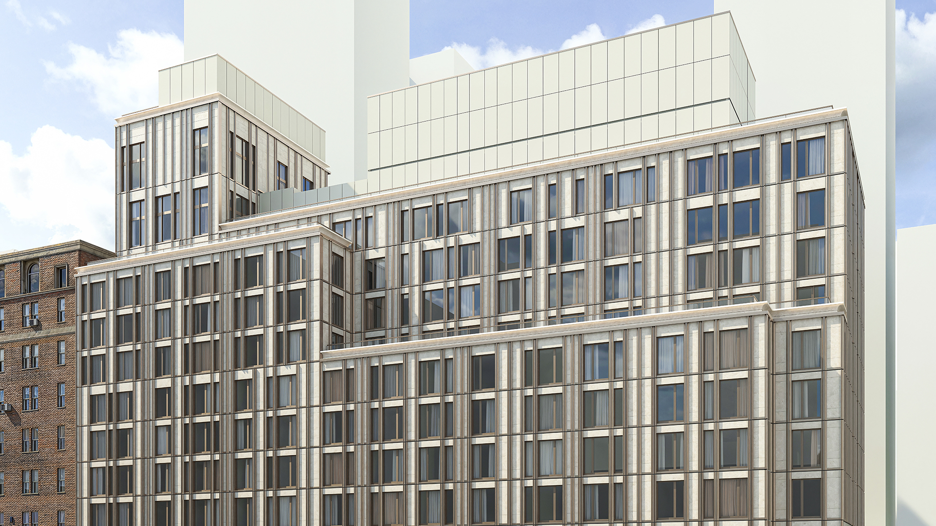
A curtain wall type in Revit holds four parameter groups: vertical grid settings, horizontal grid settings, the default panel type assignment, and the default mullion types. Grid settings include a layout rule, spacing value, justification, and angle. The layout rule determines how panels behave when wall length changes — and it's where most sequencing problems start.
Revit offers four layout rules per grid direction:
- Fixed Distance: Grid lines at a set interval. When wall length changes, unused space accumulates at one end. Panel widths stay fixed.
- Fixed Number: Wall divided into a specified number of equal panels. Panel width adjusts proportionally when wall length changes.
- Maximum Spacing: Grid lines spaced up to a maximum interval; the last panel absorbs any remainder rather than creating a short cell.
- None: No automatic grid lines. All grid lines added manually.
On a facade designed around a fixed 1,200 mm panel module — standard for many unitized curtain wall systems — Fixed Distance locks the module width regardless of wall length. On a facade where panels must always be equal in width, Fixed Number is correct but will change panel widths with every plan adjustment. Choosing the wrong rule for the design intent is a common source of unexpected panel redistribution after plan updates.
The system type does not control panel geometry, panel material, or panel detailing. Those parameters live in the panel family.
Curtain Wall Panels in Revit — System Panel Types vs Loadable Panel Families
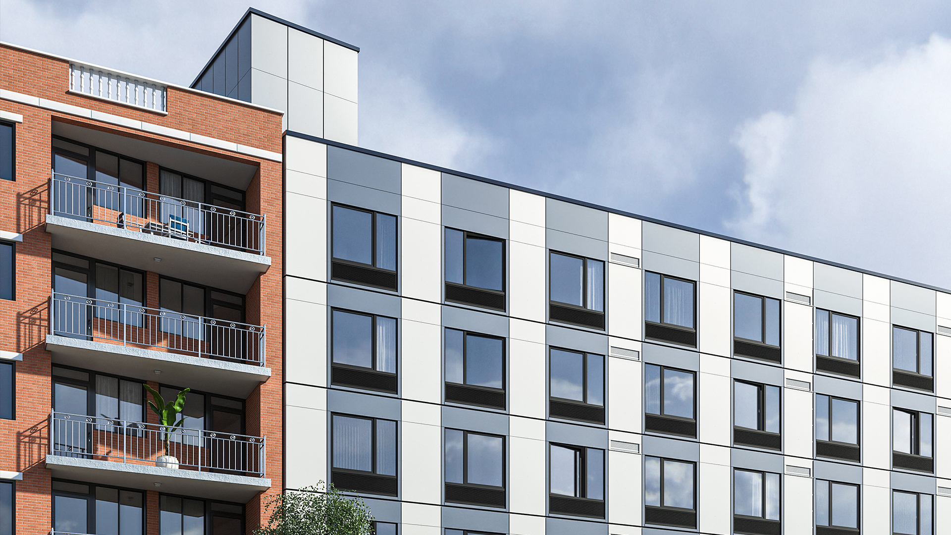
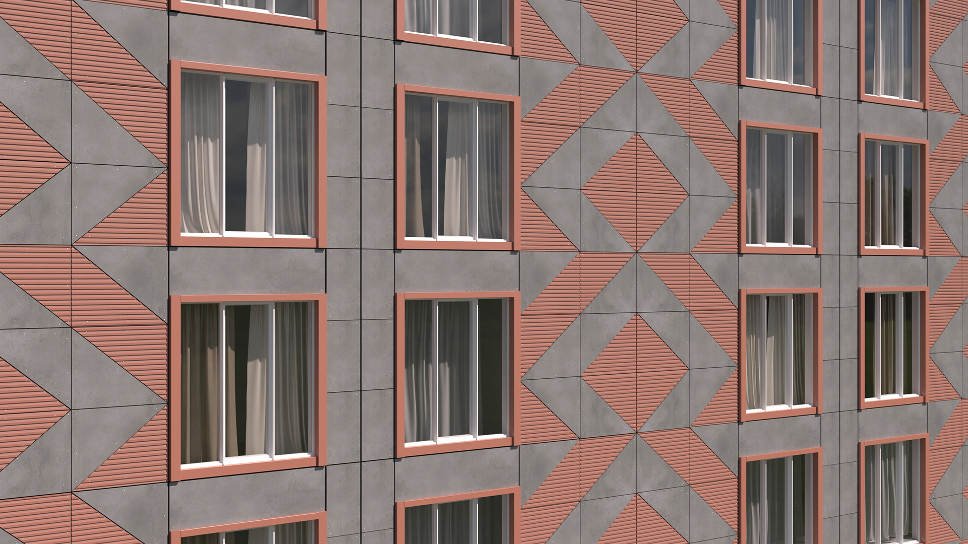
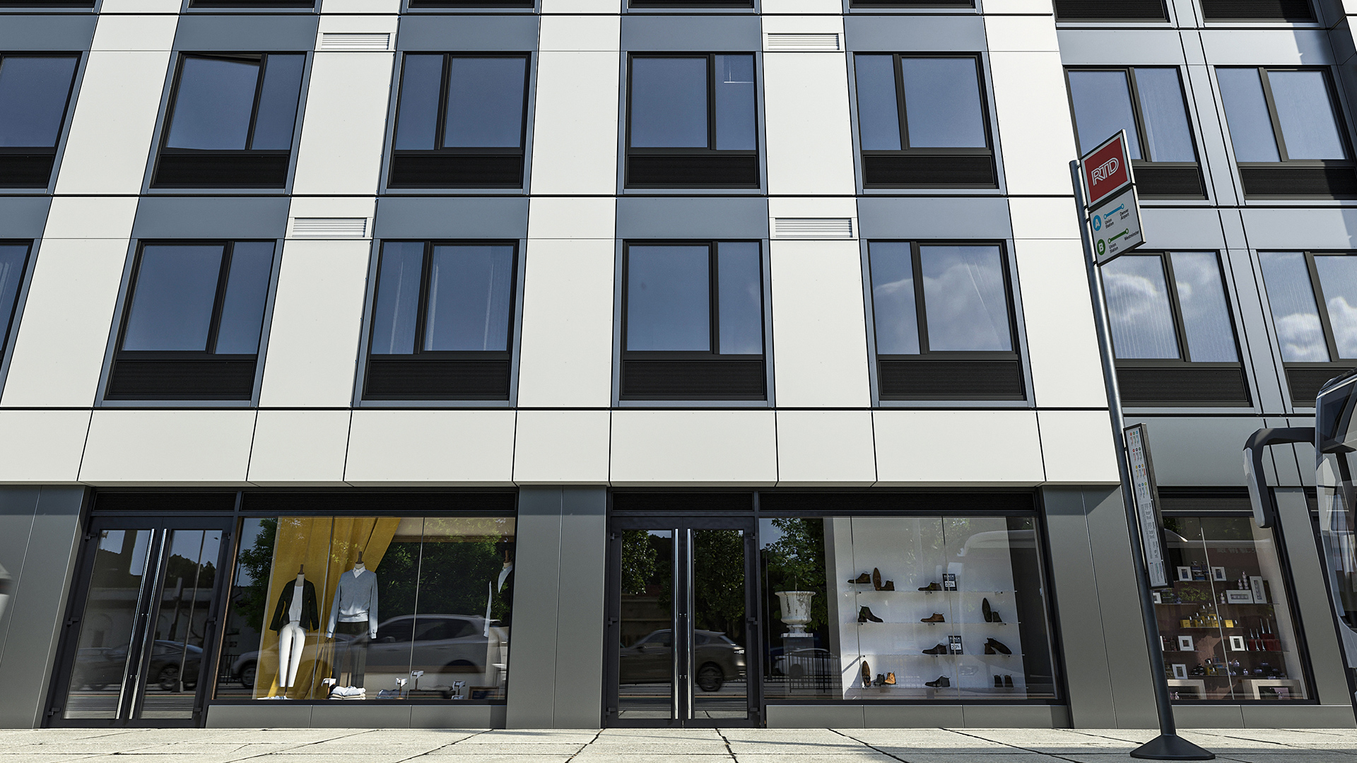
Revit ships with two built-in system panel types: Glazed (transparent) and Solid (opaque). System panel types accept basic material overrides but offer no geometry customization. For any panel requiring custom profiles, embedded window units, specific insulation layering, or spandrel detailing — as covered in spandrel panel vs vision glass — a loadable panel family is required.
Loadable curtain panel families are created in the Family Editor using the Curtain Panel.rft template. Three rules apply without exception:
The family category must be set to Curtain Panel — not Generic Model, not Wall, not any other category. A family with the wrong category loads into the project but does not appear in the panel type selector when a grid cell is selected. Revit does not flag this as an error; the family simply isn't available for assignment.
Width and height in a curtain panel family are not user-controlled parameters. The grid cell drives both dimensions. The panel family must include Left, Right, Top, and Bottom reference planes, with all geometry locked to those planes. When cell dimensions change — because grid spacing changed or wall length changed — the panel stretches or compresses to fit. This is by design; it's what allows one family to serve multiple grid configurations.
Nested components inside a panel family — window units, handles, vents — must be loadable families in their own right. Each layer of nesting adds model weight. On a large facade with 200+ panels, overloaded families compound quickly — view regeneration slows and file size balloons in proportion to nesting depth.
Mullion Types Are System Families — Their Shape Comes from a Separate Profile Family
Mullion types in Revit are system families, not loadable. They live inside the project and are configured through type properties: material, position (rectangular, circular, corner), and dimensional offsets. Mullions are created on each curtain grid segment and on wall extremities — they are configured inside the project, never loaded from an external file.
The cross-section shape of a custom mullion comes from a Mullion Profile family — a loadable family created from the Profile.rft template and loaded into the project. The mullion system family references the profile; the profile controls the extrusion shape. Two separate actions are required to set up a custom mullion: first, load the profile family; then configure the mullion type to reference that profile. Setting mullion type properties without first loading a profile family has no visible effect on the cross-section shape.
For a facade with non-standard mullion profiles — custom aluminum extrusions, for example — the profile family needs to be created and loaded before mullion type configuration begins, and the profile geometry needs to be validated against structural clearances at LOD 350. For context on where system interfaces are resolved and who is responsible, see LOD 300 vs LOD 400.
Four Places Where the System vs Loadable Model Breaks in Practice
1. Wrong family category. A curtain panel family with its category set to Generic Model will not appear in the grid cell type selector. Revit loads the family without warning — it simply isn't available for grid cell assignment. Fix: open in the Family Editor, change the category to Curtain Panel, reload into the project.
2. Editing the system type to fix a panel problem. Curtain wall type properties control grid rules and default assignments — not panel geometry or materials. If a panel looks wrong, the fix is in the loadable panel family or its instance parameters. Editing the curtain wall system type has no effect on panel shape.
3. Grid layout rule mismatch. A Fixed Number rule on a facade with a fixed panel module produces panels that change width when the plan is adjusted. Selecting the right layout rule at the start of facade modeling — before panels are detailed — prevents redistribution that requires re-documentation at a late stage.
4. Overloaded panel families. Loadable panel families with nested window units, fine-detail profiles, and multiple levels of nesting slow view regeneration on large facades. Facade teams often maintain two versions: a lightweight family for design-phase modeling and a fully detailed family for LOD 300 construction document views. For more on the cost of over-detailing at the wrong phase, see what LOD architects need at each project stage.
How the System vs Loadable Split Maps to LOD Sequencing on a Facade Project
The curtain wall family architecture aligns directly with the LOD framework — and getting the mapping wrong in either direction creates rework.
At LOD 100–200 (Schematic Design): the curtain wall system type defines the facade grid — module spacing, floor-to-floor heights, grid layout rules. Generic system panel types (Glazed, Solid) populate the cells. No manufacturer-specific loadable panel family is committed. The facade is still a design decision, not a fabrication commitment. For a phase-by-phase breakdown of what architects are expected to model and when, see what LOD architects need.
At LOD 300 (Design Development through Construction Documents): specific loadable panel families replace the generic types. Panel geometry is confirmed, materials are assigned, and dimensions are measurable. This is the architect's deliverable.
At LOD 350–400 (Pre-Fabrication through Fabrication): the facade contractor loads manufacturer-specific panel families — precise extrusion profiles, hardware specifications, anchor components. This is not the architect's responsibility. On unitized curtain wall systems with 6–12 month fabrication lead times, the architect's LOD 300 handoff is the trigger for this process. Moving to fabrication-level families before the design is approved means rebuilding the model when the design changes, not revising it — the failure mode covered in LOD 300 vs LOD 400.
How Kora Studio Grid Editor Removes the System vs Loadable Complexity at LOD 100
For architects working at LOD 100 — before any manufacturer's panel family is loaded — configuring Revit's curtain wall system type manually adds setup time at exactly the moment when facade concepts need to move fast. Panel spacing decisions, module rhythm explorations, and zone assignments should happen without navigating family categories and grid rule configuration.
Kora Studio Grid Editor lets architects define panel spacing, floor-to-floor module heights, and cladding zone assignments inside Revit using formula-driven dimension fields — without manually configuring a curtain wall system type or loading any manufacturer's panel catalog. The facade schedule, material zone assignments, and panel layout update as the design evolves. Kora Studio works exclusively with unitized curtain wall systems and supports opaque panels and panels with a window; full-height vision glass panels are outside Kora Studio's current scope.
When schematic design is complete and the facade direction is approved, the Kora Studio LOD 100 model becomes the coordination foundation for LOD 300 — not a throwaway file rebuilt because the system type was configured around the wrong module too early. For examples of how this plays out across project types, see Kora Studio facade project use cases.
If your team is spending time on system type setup before the panel module is confirmed, the issue is sequencing — not Revit. Book a demo to see what LOD 100 facade design looks like inside Revit.
FAQ
What is the difference between a curtain wall system family and a loadable curtain panel family in Revit?
A curtain wall system family — the wall type itself — is built into Revit and defines grid layout rules, default panel types, and default mullion assignments. It cannot be loaded from an external file. A loadable curtain panel family is an external .rfa file created from the Curtain Panel.rft template. It controls panel geometry, material layering, and any nested components. The system family determines which loadable panel family populates each grid cell; the loadable family controls what that panel looks like and how it behaves when cell dimensions change.
Why won't my custom curtain panel family appear in the panel type selector for a grid cell?
The most common cause is an incorrect family category. A curtain panel family must have its category set to Curtain Panel in the Family Editor. If the category is Generic Model or any other type, Revit loads the family into the project without making it available for curtain wall grid cell assignment — no error, no warning. Open the family in the Family Editor, go to Family Category and Parameters, set the category to Curtain Panel, and reload. The family should then appear in the type selector when a grid cell is selected in the curtain wall.
How do Revit curtain wall grid layout rules affect panels when wall length changes?
Grid layout rules determine how panels respond to wall length changes. Fixed Distance holds panel widths constant and creates a gap at one end when the wall length changes — useful for facades with a fixed panel module. Fixed Number keeps the number of panels constant and adjusts panel widths proportionally — useful when panels must always be equal in width. Maximum Spacing limits panel width to a maximum value and adjusts the last panel rather than creating a gap. None requires all grid lines to be placed manually. Choosing the wrong rule for the design intent is a common source of unexpected redistribution after plan updates. For more on module decisions in unitized facade systems, see unitized vs stick-built curtain wall.
What is the difference between a Revit mullion type and a curtain wall panel family?
Mullion types and curtain panel families are separate elements with different architectures in Revit. A mullion type is a system family — defined inside the project, configured through type properties, with cross-section shape coming from a separately loaded Mullion Profile family. A curtain panel family is a loadable .rfa file that fills the rectangular cells created by the curtain wall grid. Mullions run along grid lines; panels fill the cells between them. They are assigned separately: mullion types through the curtain wall system type or by selecting individual grid segments; panel types through the default assignment in the system type or by selecting individual cells.
At what project phase should architects switch from generic system panel types to specific loadable curtain panel families?
The transition typically happens at the start of Design Development, when the facade module is confirmed and panel zones are approved. Through Schematic Design, generic system panel types — Glazed and Solid — are sufficient for grid layout, area calculations, and LOD 100–200 documentation. Loading specific loadable panel families during Schematic Design ties the model to components that may need to be replaced if the design direction changes — turning a panel swap into a model rebuild. The BIM Execution Plan should define which panel families are required, at which phase, and by which party. For how LOD targets should be assigned per phase, see what LOD architects need.