BIM — Building Information Modeling — in facade design means building a data-rich 3D model that serves as the single source of truth for the facade system throughout the project lifecycle: from design intent through fabrication documentation.
In practice, most teams use Revit for facade BIM work. But having a Revit model isn't the same as having a BIM facade workflow. BIM is not software — it's a process: how the model is structured, who maintains it, what information it carries, and how it's used to make decisions and produce documentation at each phase.
This guide covers what a functional BIM facade workflow looks like, who is responsible for what, which tools support each phase, and where the process typically fails.
What BIM Means for Facade Design
The core value of BIM in facade design is coordination — making it possible for the facade system to be designed, analyzed, documented, and handed off to fabrication without the information gaps and translation errors that generate RFIs, rework, and schedule delays.
A BIM facade model that is working correctly does four things:
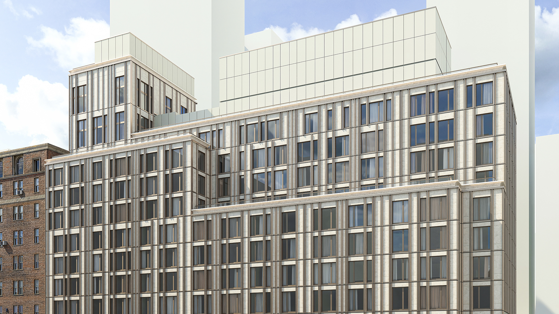
It accurately represents the system. Panel modules, grid logic, corner conditions, interface geometry — the model reflects what would actually be built, not a graphic approximation of it. At schematic design, accuracy means the system logic is correct. At design development, it means the geometry is buildable. At construction documents, it means the model is coordination-ready.
It carries the right information. Panel types, materials, thermal performance specs, quantities — this information lives in the model, not in a separate spreadsheet. When the model is updated, the information updates with it.
It produces useful documentation. Schedules, glazing ratios, facade elevations, and coordination drawings come from the model. Documentation is not maintained separately — it's generated from the single source of truth.
It supports decision-making. When a design decision needs to be made — which panel module to use, how to handle a corner condition, whether a glazing ratio meets code — the model provides the data to make an informed choice.
Who Does What: Roles in a BIM Facade Workflow
BIM facade work involves three main roles, each with distinct responsibilities.
The Design Architect
The design architect is responsible for the facade concept and design intent: the grid logic, the panel mix, the aesthetic language of the facade. In BIM terms, this means making design decisions that are expressible in a model — panel modules that work with the structural grid, corner conditions that are physically buildable, glazing ratios that meet code.
The design architect doesn't need to build the full coordination model, but does need to make decisions that are compatible with the coordination requirements. A facade concept that can't be modeled correctly is a coordination problem waiting to happen.
In Revit, the design architect typically works at LOD 100–200 during schematic design and design development. The model at this stage should capture the system logic accurately, even if the level of detail is low. See What LOD Do Architects Actually Need for Facade Design? for guidance on LOD by phase.
The BIM Manager
The BIM manager (or facade BIM lead) owns the coordination model: the Revit model that is used for consultant coordination, documentation, and handoff. BIM coordination standards and open file exchange formats — including IFC — are maintained by buildingSMART International. Responsibilities include:
- Setting up and maintaining the curtain wall model with accurate geometry
- Managing panel families and parameters
- Coordinating the facade model with structural and mechanical models
- Producing and maintaining facade schedules, quantities, and glazing ratios
- Ensuring the model is at the correct LOD for each project phase
- Managing the handoff from design model to fabrication documentation
The BIM manager is the person who makes the model work. They need both Revit expertise and an understanding of the facade system — how unitized panels are installed, what information fabricators need, what coordination the structural engineer requires. See LOD in BIM: What LOD 100, 200, 300, and 400 Mean for the LOD framework that governs handoff.
The Facade Fabricator
The fabricator needs the BIM model to produce shop drawings, manufacturing drawings, and installation sequences. Their requirements are different from the design team's: they need panel-level geometry, anchor positions, structural interface dimensions, and joint profiles — information that may not be in the design model even at LOD 300.
The gap between what the design team's model contains and what the fabricator needs is one of the most common sources of RFIs and coordination time on facade projects. The BIMForum LOD Specification defines precisely what information each model element must contain at LOD 300 and LOD 400 to close this gap. Closing this gap requires either extending the design model to LOD 400 (which is typically the fabricator's responsibility) or ensuring the LOD 300 handoff package contains everything the fabricator needs to start LOD 400 work without going back to the design team.
For more on this handoff, see From Design to Fabrication: How to Close the Gap and LOD 300 vs LOD 400: Where Facade Design Ends and Fabrication Begins.
Key BIM Workflows in Facade Projects
Schematic Design: System Logic Modeling
The goal at schematic design is to establish the system logic correctly — panel module, grid origin, corner conditions, interface geometry — at LOD 100. The model doesn't need to be detailed, but it needs to be structurally honest: the panel module should accommodate the structural grid, the corner conditions should be physically possible, and the facade should be checkable against zoning requirements (height, setbacks, glazing ratios).
This is also when the structural engineer should first see the facade grid, so that the structural column layout and anchor spacing can be coordinated before the structural system is locked.
Design Development: Coordination and Documentation Setup
Design development is where the facade model moves from system logic to buildable geometry. The BIM manager takes the design architect's concept and builds a coordination model: panels sized to match the structural grid, corners resolved to a buildable detail, mechanical interfaces coordinated, schedules and quantities set up.
This is also the phase where performance checks happen: daylight analysis, thermal performance verification, code compliance for glazing ratios. These checks require the model to carry accurate area and material data.
Changes in design development are still manageable, but they are significantly more expensive than changes at schematic design. The goal is to resolve all major system decisions before entering construction documents.
Construction Documents: Documentation and Handoff
At construction documents, the BIM model is the basis for facade schedules, specification references, and coordination drawings. The model should be at LOD 300: precise geometry, confirmed materials, coordination-ready.
The handoff package to the facade fabricator typically includes the Revit model or exported IFC, facade schedules, glazing schedule, and structural anchor layout. The quality of this handoff determines how much back-and-forth is required during shop drawing preparation.
Tools for BIM Facade Work
Revit is the baseline for facade BIM work in most firms. It handles the model, the documentation, and the schedule generation. Its curtain wall tools work well for standard stick-built facades; for unitized systems, extensions are typically needed. See Revit Curtain Wall: Complete Reference for the full toolset overview.
Kora Studio extends Revit for the design-phase workflow on unitized curtain wall and facade systems — automating grid setup, panel assignment, schedule generation, and Light and Air calculations. It reduces the time and effort required to keep the facade model accurate through design iterations. Teams using Kora Studio report 68% faster design iterations and 84% fewer RFIs.
Navisworks or BIM 360 Clash is used for multi-discipline coordination — checking the facade model against structural, mechanical, and plumbing models for clashes.
FenestraPro or similar analysis tools handle performance analysis — daylight, solar, thermal — within the Revit model.
AGACAD and similar fabrication tools handle the LOD 400 documentation that fabricators need for shop drawings.
How to Tell If Your BIM Facade Workflow Is Working
A BIM facade workflow is working when:
- The model is the source of truth for all facade documentation — no parallel spreadsheets maintained separately
- Schedule updates are synchronized with model changes, not done manually after the fact
- Coordination with structure and MEP happens at design development, not during construction documents
- The LOD 300 handoff package is complete enough that the fabricator can start LOD 400 work without major back-and-forth
- RFIs from the fabricator are about non-standard conditions, not about information that should have been in the design package
A BIM facade workflow is not working when schedules lag the model, when coordination happens late because the model wasn't ready earlier, or when the fabricator's first RFI batch contains questions about basic geometry, panel sizing, or interface conditions.
Book a demo to see how Kora Studio fits into a BIM facade workflow, or explore kora.studio/use-cases for project type examples.
FAQ
What is BIM in facade design?
BIM in facade design means building a data-rich 3D model that serves as the single source of truth for the facade system throughout the project — from design intent through fabrication documentation. The model carries information (panel types, materials, quantities, thermal data) that is used to produce documentation, coordinate with other disciplines, and support design decisions at each phase.
What is the BIM manager's role in a facade project?
The BIM manager owns the coordination model: they set up and maintain the Revit curtain wall model, manage panel families and parameters, coordinate the facade model with structural and mechanical disciplines, produce facade schedules and quantities, and manage the handoff from design model to fabrication documentation.
What is LOD in facade BIM, and why does it matter?
LOD (Level of Development) defines what information a model element contains at each project phase. LOD 100 is conceptual — the system logic is correct but detail is low. LOD 300 is design-complete — precise geometry, confirmed materials, coordination-ready. LOD 400 is fabrication-ready — every component is modeled to manufacturing specifications. Using the right LOD at the right phase prevents over-modeling early and ensures the handoff package contains what downstream teams need.
When should facade coordination with structural engineering begin?
At schematic design — specifically, when the facade grid module and corner conditions are first established. The structural column layout and anchor spacing need to be compatible with the facade module before the structural system is locked. Starting coordination at design development or later means making changes to a structural system that is already partially designed, which is more expensive and time-consuming.
What causes the most RFIs in facade BIM projects?
The most common sources are information gaps in the LOD 300 handoff package (missing anchor positions, unspecified joints, undefined interfaces), documentation that lags the model (schedules that don't match current panel assignments), and coordination failures between the facade grid and the structural system that weren't resolved during design.